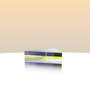

A polarizing beamsplitter prism is an optical element used to separate the horizontal and vertical polarizations of light.
The polarizing beam splitter prism is formed by coating a multi-layer film structure on the inclined surface of the right angle prism, and then gluing it into a cubic structure, using the property that the transmittance of P-polarized light is 1 and the transmittance of S-polarized light is less than 1 when the light is incident at Brewster’s angle. After the light passes through the multilayer film structure at Brewster’s angle for many times, it reaches an optical element in which the P-polarized component is completely transmitted, and most of the S-polarized component is reflected (at least 90% or more).
The polarizing beam splitter prism is used to separate the horizontal polarization and vertical polarization of a beam of light. The ratio of the transmittance of P light to S light is greater than 1000, and the transmittance of P light is guaranteed to be above 90%. It has the characteristics of low stress, high extinction ratio, good imaging quality and small beam deflection angle. The wavelengths cover the 420-1600nm region. It can be used for polarization, polarization analysis, light intensity adjustment and other occasions.
| Specifications | |
| Material | N-BK7; Fused Silica; etc. |
| Dimension X×Y: | 1×1mm~50×50mm |
| Dimension tolerance | ±0.03mm to 0.1mm |
| Angle tolerance | <5 arc sec. to 20 arc sec. |
| Clear aperture | >85% to 90% of dimension |
| Surface quality | 60/40, 40/20, 20/10 scratch/dig |
| Flatness (perØ25.4mm) | λ/10 to λ/4 @632.8nm |
| T/R(for random polarization)
T=(Ts+Tp)/2;R=(Rs+Rp)/2 |
T/R=50/50±2% |
| Bevel(face width×45°) | 0.1mm to 0.2mm |
| Coating | Upon clients’ request |
| Wavelength(nm) | T/R |
| 532 | T/R=50/50±2% |
| 632 | T/R=50/50±2% |
| 670 | T/R=50/50±3% |
| 780 | T/R=50/50±3% |
| 1064 | T/R=50/50±3% |
| 1310 | T/R=50/50±3% |
| 400-700 | T/R=50/50±3% |
| 659-900 | T/R=50/50±3% |
| 900-1200 | T/R=50/50±3% |
| 1200-1600 | T/R=50/50±3% |